
Probably you have read my super filter design. It aims to augment projects starting from a setup like pictured below.

The idea is to leverage my clock library to provide a super filter.
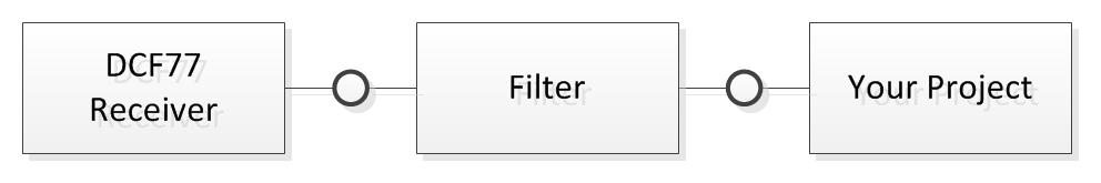
Inside this filter uses the library and feeds its results into a DCF77 synthesizer.

Pretty simple and obvious once the hard work of implementing such a library is done. However one of my readers complained that the result performed significantly worse than the library. This appears surprising at first glance but it was actually a design choice which might by argued about. Before this issue can be resolved you need to understand the different internal states of the clock library. These states were introduced with the local clock and are described at this experiment in greater detail.
The point is that the library has an internal state engine that follows the diagram below.
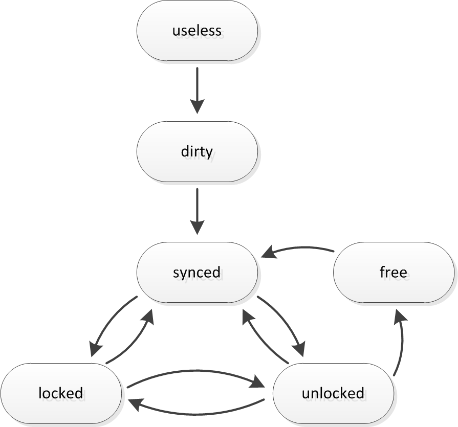
Depending on the internal state the library will have more or less accurate time. Synced is most accurate, then comes locked, unlocked and free. Dirty might be accurate but useless is almost never accurate. The point was that I choose to only synthesize the signal if the internal state was “locked” or “synced”. In all other cases I was just passing the signal as it was received. This was to guarantee that the filter would not create “leaps” in its output (except wrongly placed 1s leaps for leap seconds). However the library keeps pretty accurate time even in free mode, especially if it was able to auto tune for a week or so. So the expectation was that even when the signal gets lost the synthesizer should still provide usable output. The impact of this is that the clock might leap an arbitrary amount of time once it resyncs. OK, I am exagerating. It would probably leap less than 1s for each week it was runnning “free”. Still this might be unacceptable for some projects.
I see some reasons why leaps may be unacceptable. One reason are “alarm triggers.” I would suggest to change those to “alarm states” like in my “Electro Mechanical” Time Switch experiment. However this might be no option for an existing project. Another reason are projects that will somehow use DCF77 for calibration purposes and rely on the knowledge of signal loss to switch to their internal clock.
On the other hand there may be projects that use just “naive sync with DCF77”. For those synthesizing the time signal even in “free” state would be an improvement.
Since I can not know what a project really would need my new super filter will provide just all options. It provides three different outputs.
- Filtered Output – This is the only option of the original Super Filter – If the clock is at least in state “locked” the output is synthesized and thus 100% clean. The phase will be spot on but it might leap for 1s at unexpected times if can not properly decode the leap second anouncement bit while a leap second is actually scheduled. In less than “locked” states it will pass the signal through. This is the most defensive modes which provides least filtering. If your DCF77 signal is not total crap it may be more than sufficient.
- Semi Synthesized Output – This is almost the same as above. However it keeps synthesizing in “unlocked” mode. That is it may allow the phase of the second ticks to drift up to 0.3 s before it starts to pass the signal just through. It is a middle ground. I have no clue if someone will need it but it was almost no additional effort to implement this.
- Synthesized Output – This is the most agressive filter mode. After its initial sync it will synthesize no matter what the internal state is. This is probably what some of my readers had in mind when they read about the super filter. However beware: if you do not evaluate the diff pin you will never know that it may be running “free” and thus drifting out of sync slowly. Of course if the signal is reasonable every once in a while it will resync though.
If you look into the code you will notice that it is almost the same as before. Only the pin setup and output handling basically trippled. There are also options to disable some of the output modes. I strongly recommend to disable the undesired modes because unless the signal is really really poor the behaviour of the modes is exactly the same.
//
//  www.blinkenlight.net
//
//  Copyright 2015 Udo Klein
//
//  This program is free software: you can redistribute it and/or modify
//  it under the terms of the GNU General Public License as published by
//  the Free Software Foundation, either version 3 of the License, or
//  (at your option) any later version.
//
//  This program is distributed in the hope that it will be useful,
//  but WITHOUT ANY WARRANTY; without even the implied warranty of
//  MERCHANTABILITY or FITNESS FOR A PARTICULAR PURPOSE. See the
//  GNU General Public License for more details.
//
//  You should have received a copy of the GNU General Public License
//  along with this program. If not, see http://www.gnu.org/licenses/

#include <dcf77.h>


const uint8_t dcf77_analog_sample_pin = 5;
const uint8_t dcf77_sample_pin = 19; // A5
const uint8_t dcf77_inverted_samples = 1;
const uint8_t dcf77_analog_samples = 1;

const uint8_t dcf77_monitor_pin = 18; // A4

const bool provide_filtered_output = true;
const uint8_t dcf77_filtered_pin          = 12;
const uint8_t dcf77_inverted_filtered_pin = 11;
const uint8_t dcf77_filter_diff_pin       = 7;

const bool provide_semi_synthesized_output = true;
const uint8_t dcf77_semi_synthesized_pin          = 16;
const uint8_t dcf77_inverted_semi_synthesized_pin = 15;
const uint8_t dcf77_semi_synthesized_diff_pin     = 14;

const bool provide_synthesized_output = true;
const uint8_t dcf77_synthesized_pin          = 6;
const uint8_t dcf77_inverted_synthesized_pin = 5;
const uint8_t dcf77_synthesized_diff_pin     = 4;

const uint8_t dcf77_second_pulse_pin = 10;


const uint8_t dcf77_signal_good_indicator_pin = 3;

volatile uint16_t ms_counter = 0;
volatile DCF77::tick_t tick = DCF77::undefined;


template <bool enable, uint8_t threshold,
          uint8_t filtered_pin, uint8_t inverted_filtered_pin, uint8_t diff_pin>
void set_output(uint8_t clock_state, uint8_t sampled_data, uint8_t synthesized_signal)
{
    if (enable) {
        const uint8_t filtered_output = clock_state < threshold? sampled_data: synthesized_signal;
        digitalWrite(filtered_pin, filtered_output);
        digitalWrite(inverted_filtered_pin, !filtered_output);
        digitalWrite(diff_pin, filtered_output ^ sampled_data);
    }
}

uint8_t sample_input_pin() {
    const uint8_t clock_state = DCF77_Clock::get_clock_state();
    const uint8_t sampled_data =
        dcf77_inverted_samples ^ (dcf77_analog_samples? (analogRead(dcf77_analog_sample_pin) > 200)
                                                      : digitalRead(dcf77_sample_pin));

    digitalWrite(dcf77_monitor_pin, sampled_data);
    digitalWrite(dcf77_second_pulse_pin, ms_counter < 500 && clock_state>=DCF77_Clock::locked);

    const uint8_t synthesized_signal =
        tick == DCF77::long_tick  ? ms_counter < 200:
        tick == DCF77::short_tick ? ms_counter < 100:
        tick == DCF77::sync_mark  ?  0:
                                           // tick == DCF77::undefined --> default handling
                                           // allow signal to pass for the first 200ms of each second
                                          (ms_counter <=200 && sampled_data) ||
                                           // if the clock has valid time data then undefined ticks
                                           // are data bits --> first 100ms of signal must be high
                                           ms_counter <100;

    set_output<provide_filtered_output, DCF77_Clock::locked,
              dcf77_filtered_pin, dcf77_inverted_filtered_pin, dcf77_filter_diff_pin>
              (clock_state, sampled_data, synthesized_signal);

    set_output<provide_semi_synthesized_output, DCF77_Clock::unlocked,
               dcf77_semi_synthesized_pin, dcf77_inverted_semi_synthesized_pin, dcf77_semi_synthesized_diff_pin>
               (clock_state, sampled_data, synthesized_signal);

    set_output<provide_synthesized_output, DCF77_Clock::free,
               dcf77_synthesized_pin, dcf77_inverted_synthesized_pin,  dcf77_synthesized_diff_pin>
               (clock_state, sampled_data, synthesized_signal);


    ms_counter+= (ms_counter < 1000);

    return sampled_data;
}


void output_handler(const DCF77_Clock::time_t &decoded_time) {
    // reset ms_counter for 1 Hz ticks
    ms_counter = 0;

    // status indicator --> always on if signal is good
    //                      blink 3s on 1s off if signal is poor
    //                      blink 1s on 3s off if signal is very poor
    //                      always off if signal is bad
    const uint8_t clock_state = DCF77_Clock::get_clock_state();
    digitalWrite(dcf77_signal_good_indicator_pin,
                 clock_state >= DCF77_Clock::locked  ? 1:
                 clock_state == DCF77_Clock::unlocked? (decoded_time.second.digit.lo & 0x03) != 0:
                 clock_state == DCF77_Clock::free    ? (decoded_time.second.digit.lo & 0x03) == 0:
                                                       0);
    // compute output for signal synthesis
    DCF77::time_data_t now;
    now.second                    = BCD::bcd_to_int(decoded_time.second);
    now.minute                    = decoded_time.minute;
    now.hour                      = decoded_time.hour;
    now.weekday                   = decoded_time.weekday;
    now.day                       = decoded_time.day;
    now.month                     = decoded_time.month;
    now.year                      = decoded_time.year;
    now.uses_summertime           = decoded_time.uses_summertime;
    now.leap_second_scheduled     = decoded_time.leap_second_scheduled;
    now.timezone_change_scheduled = decoded_time.timezone_change_scheduled;

    now.undefined_minute_output                         = false;
    now.undefined_uses_summertime_output                = false;
    now.undefined_abnormal_transmitter_operation_output = false;
    now.undefined_timezone_change_scheduled_output      = false;

    DCF77_Encoder::advance_minute(now);

    tick = DCF77_Encoder::get_current_signal(now);
}

void setup_serial() {
    Serial.begin(115200);
}

void output_splash_screen() {
    using namespace DCF77_Encoder;

    Serial.println();
    Serial.println(F("DCF77 Superfilter 1.1.0"));
    Serial.println(F("(c) 2015 Udo Klein"));
    Serial.println(F("www.blinkenlight.net"));
    Serial.println();
    Serial.print(F("Sample Pin:               ")); Serial.println(dcf77_sample_pin);
    Serial.print(F("Inverted Mode:            ")); Serial.println(dcf77_inverted_samples);
    Serial.print(F("Analog Mode:              ")); Serial.println(dcf77_analog_samples);
    Serial.print(F("Monitor Pin:              ")); Serial.println(dcf77_monitor_pin);
    Serial.println();

    if (provide_filtered_output) {
        Serial.println(F("Filtered Output"));
        Serial.print(F("    Filtered Pin:         ")); Serial.println(dcf77_filtered_pin);
        Serial.print(F("    Diff Pin:             ")); Serial.println(dcf77_filter_diff_pin);
        Serial.print(F("    Inverse Filtered Pin: ")); Serial.println(dcf77_inverted_filtered_pin);
        Serial.println();
    }

    if (provide_semi_synthesized_output) {
        Serial.println(F("Semi Synthesized Output"));
        Serial.print(F("    Filtered Pin:         ")); Serial.println(dcf77_semi_synthesized_pin);
        Serial.print(F("    Diff Pin:             ")); Serial.println(dcf77_semi_synthesized_diff_pin);
        Serial.print(F("    Inverse Filtered Pin: ")); Serial.println(dcf77_inverted_semi_synthesized_pin);
        Serial.println();
    }

    if (provide_synthesized_output) {
        Serial.println(F("Synthesized Output"));
        Serial.print(F("    Filtered Pin:         ")); Serial.println(dcf77_synthesized_pin);
        Serial.print(F("    Diff Pin:             ")); Serial.println(dcf77_synthesized_diff_pin);
        Serial.print(F("    Inverse Filtered Pin: ")); Serial.println(dcf77_inverted_synthesized_pin);
        Serial.println();
    }

    Serial.print(F("Second Pulse Pin:         ")); Serial.println(dcf77_second_pulse_pin);
    Serial.print(F("Signal Good Pin:          ")); Serial.println(dcf77_signal_good_indicator_pin);

    Serial.println();

    Serial.println();
    Serial.println(F("Initializing..."));
    Serial.println();
};

void setup_pins() {
    if (provide_filtered_output) {
        pinMode(dcf77_filtered_pin, OUTPUT);
        pinMode(dcf77_filter_diff_pin, OUTPUT);
        pinMode(dcf77_inverted_filtered_pin, OUTPUT);
    }

    if (provide_semi_synthesized_output) {
        pinMode(dcf77_semi_synthesized_pin, OUTPUT);
        pinMode(dcf77_semi_synthesized_diff_pin, OUTPUT);
        pinMode(dcf77_inverted_semi_synthesized_pin, OUTPUT);
    }

    if (provide_synthesized_output) {
        pinMode(dcf77_synthesized_pin, OUTPUT);
        pinMode(dcf77_synthesized_diff_pin, OUTPUT);
        pinMode(dcf77_inverted_synthesized_pin, OUTPUT);
    }

    pinMode(dcf77_monitor_pin, OUTPUT);
    pinMode(dcf77_signal_good_indicator_pin, OUTPUT);
    pinMode(dcf77_second_pulse_pin, OUTPUT);
    pinMode(dcf77_sample_pin, INPUT);
    digitalWrite(dcf77_sample_pin, HIGH);
}


void setup_clock() {
    DCF77_Clock::setup();
    DCF77_Clock::set_input_provider(sample_input_pin);
    DCF77_Clock::set_output_handler(output_handler);
}

void setup() {
    setup_serial();
    output_splash_screen();
    setup_pins();
    setup_clock();
}

void loop() {
    DCF77_Clock::time_t now;

    DCF77_Clock::get_current_time(now);

    if (now.month.val > 0) {
        Serial.println();
        Serial.print(F("Decoded time: "));

        DCF77_Clock::print(now);
        Serial.println();
    }

    DCF77_Clock::debug();
}
If you look at the code there is almost nothing new compared to the old super filter. Of course the output handling basically trippled as it now provides 3 outputs. The only noteworthy thing is the template function set_output. Notice that the if statement is NOT evaluated at run time but at compile time. As a consequence the compiler will optimize the function away for the modes that are not in use.


Hi Udo, thank you very much – I’ve successfully tested your awesome Superfilter with my own clock project based on Atmega 644/1284. Now I am thinking about how to get the status information out of the Superfilter into the “main” processor (perhaps to display signal quality on grafic display). Sure I could read the status line (LED) with a free port but I don’t think that this would be the best way. What do you think about a serial connection which could deliver more information from the Superfilter with some basic commands?
During repeated tests with (really) poor DCF-77 signal (blink 1s-on/3s-off) I’ve noticed a wrong time after sync (was done after a couple of hours) with main processor using the “synthesized” output of the Superfilter (which is running on an Arduino Nano with 16MHz Quartz). Any Idea?
Now I am using the “filtered” output because I deployed an RTC (DS3232) on the main board to preserve precise time even DCF signal is poor or lost and to have the valid time immediately after startup or power loss.
Best regards
Ralph
Hi Ralph, in order to analyze this I need more information. Which version of my library are you running? In order to get an overall idea of your signal situation. Could you please provide me a log of the received signal logged by the “Swiss Army Debug Helper” sketch in Mode “Dm” for at least an hour. Then I would need the log output of the super filter running long enough till it reaches a state where you problem occurs. These two logs should allow me to infer what is going on.
Of course you can extend the superfilter with more information. However why don’t you then just ditch the superfilter and use the library directly in the main CPU? If you are afraid if you have sufficient processing power just switch to Arduino Due / ARM processor. This has way more computational power than two ATmegas combined and overall system complexity would go down.
Hi Udo, thanks a lot for your fast reply. While setting up some test I’ve got some strange results – using Arduino IDE 1.8.2 and your latest Library version 3.1.8. First I’ve noticed some Compiler warnings but can’t judge if this is really important or not. After uploading the code to the board it seams ok for some minutes. The DCF-Signal was good (for this test). So I’ve got the status from the debugger with the current (valid) time 00:02:58.
0 ??.05.03(3,?)00:02:57 MEZ 0,0 0 p(2958-0:184) s(23-2:5) m(10-6:1) h(8-4:1) wd(6-4:0) D(8-6:0) M(8-6:0) Y(8-7:0) 4,2,2,255
[1] 191, +———+——–9XXXXXXXXX3+———+———+———+———+———+———+———
[2] 191, +———+———+———+———+———+———+———+———+———+———
0 17.05.03(3,3)00:02:58 MEZ 0,0 0 p(2970-0:185) s(23-2:5) m(10-6:1) h(8-4:1) wd(6-4:0) D(8-6:0) M(8-6:0) Y(8-6:0) 4,2,2,255
[1] 192, +———+——-5XXXXXXXXXX6+———+———+———+———+———+———+———
[2] 192, +———+———+———+———+———+———+———+———+———+———
However some seconds later the disappeared:
0 17.05.03(?,3)00:03:57 MEZ 0,0 0 p(3507-0:219) s(31-2:5) m(14-12:0) h(12-6:1) wd(7-6:0) D(12-9:0) M(12-9:0) Y(12-10:0) 6,3,1,255
[1] 251, +———+———+8XXXXXXXXXX6——-+———+———+———+———+———+———
[2] 251, +———+———+———+———+———+———+———+———+———+———
0 ??.05.03(?,?)00:03:58 MEZ 0,0 0 p(3515-0:219) s(31-2:5) m(14-12:0) h(12-6:1) wd(7-6:0) D(12-9:0) M(12-9:0) Y(12-11:0) 6,3,1,255
[1] 252, +———+———+8XXXXXXXXX6——–+———+———+———+———+———+———
[2] 252, +———+———+———+———+———+———+———+———+———+———
and later even the minute
0 ??.05.03(3,?)00:05:28 MEZ 0,0 0 p(4023-0:251) s(41-7:6) m(18-16:0) h(8-4:1) wd(10-8:0) D(12-10:0) M(14-10:1) Y(14-14:0) 8,3,1,255
[1] 342, +———+———+—-8XXXXXXXXXXX—+———+———+———+———+———+———
[2] 342, +———+———+———+———+———+———+———+———+———+———
0 ??.05.03(3,?)00:??:29 MEZ 0,0 0 p(4030-0:251) s(41-7:6) m(20-20:0) h(8-4:1) wd(10-8:0) D(12-10:0) M(14-10:1) Y(14-14:0) 8,3,1,255
[1] 343, +———+———+—-9XXXXXXXXXX8—+———+———+———+———+———+———
[2] 343, +———+———+———+———+———+———+———+———+———+———
and so on … and then here are the wrong numbers …
0 77.07.??(7,?)??:??:19 MEZ 0,0 0 p(4139-28:255) s(75-0:12) m(36-36:0) h(60-60:0) wd(42-27:2) D(57-57:0) M(42-29:2) Y(63-52:2) 8,14,18,255
[1] 1353, +———+———+———+———+———+———+——–5XXXXXXXXXX2———+———
[2] 1353, +———+———+———+———+———+———+———+———+———+———
Now I am not sure if I’ve got wrong. I will restart the test now and will see in the morning which status will achieved.
BTW I’ve tried the IDE 1.8.0 and 1.6.7 with the similar results. In the beginning I’ve used the library Version 3.0 with IDE 1.6.7 to avoid the Preprocessor Issue.
Best Regards
Ralph
P.S: Simple question – how can I send you the log files?
Until you send me a copy of the warnings and tell me which settings (Host PC Operating System, target board) I can not judge either. With regard to the logs: email or github are both fine.
I could identify that the problem came from the Arduino Nano HW Modul itself (imported directly from China). Trying another HW Module while using the same Library version (3.1.8) and SW environment (IDE 1.8.2 running on Win7/64bit) I could get a running Filter without any problems now – works very stable even if the DCF signal is noisy.
The Compiler warnings are regarding the usage of possibly uninitialized variables – probaply not relevant – are seen with Compiler SW “show warning = all”:
dcf77.cpp:1639:69: warning: ‘precision’ may be used uninitialized in this function [-Wmaybe-uninitialized] .. eeprom_write_byte((uint8_t *)(eeprom++), (uint8_t) precision);
dcf77.cpp:1688:49: warning: ‘adjust’ may be used uninitialized in this function [-Wmaybe-uninitialized] .. ( confirmed_precision == 1 &&
Regarding ARM processor I will evaluate if your Library and my project will work together on this platform (Arduino Due already ordered) soon. Of course this will be a new challenge but the extended capabilities and the additional memory!! are worth. If this will be successfull I will develop a new PCB for such a wall mounted LED Clock as I already have with a lot of additional features (e.g. sensors, remote control, sound) and an industrially manufactured aluminum casing. If you are interested I would discuss the project if I am ready with the new design.
Last but not least I will continue the testing of the superfilter (blackbox) on my current clock design. Again thank you very much.
Best regards
Ralph
You may ignore the warnings. The values are either properly initialized or it is the task of the function to fill the them. In both cases the warning does not apply.
Hi Udo, this morning I’ve tried another Arduino (Nano) module which was programmed last week (Library Version 3.1.4) and this is working ok. See the output below:
0 17.05.03(3,3)07:10:57 MEZ 0,0 0 p(6125-0:255) s(39-2:7) m(20-12:2) h(24-16:2) wd(12-8:1) D(16-12:1) M(16-12:1) Y(16-13:0) 8,4,4,255
[1] 316, +———+——-9XXXXXXXXX6-+———+———+———+———+———+———+———
[2] 316, +———+———+———+———+———+———+———+———+———+———
Decoded time: 17-05-03 3 07:09:59 CEST ..
5 17.05.03(3,3)07:10:58 MESZ 0,0 2 p(6144-0:255) s(39-2:7) m(20-12:2) h(24-16:2) wd(12-8:1) D(16-12:1) M(16-12:1) Y(16-12:1) 8,4,4,255
[1] 317, +———+——5XXXXXXXXXXX3+———+———+———+———+———+———+———
[2] 317, +———+———+———+———+———+———+———+———+———+———
Signal good LED is on – so with this setup I will now try to repeat the issue with the poor DCF signal which results in a wrong time after a couple of hours.
I am wondering why its was not possible to program a new Modul with the latest SW Version yesterday. Perhaps I did a mistake or there is something wrong with the SW provision. I’ve used the Library Manager to install the Software on a WIndos 7 (64bit) System in both ways (add .zip Library with manually download from Github and Manage Library). Same result as described.
BTW: I will check my project on an ARM processor although I’ve already have a PCB designed for Atmega. Because I need to add the superfilter I am thinking about a redesign and therefore its a good time to switch to another (more powerful) processor. Thanks a lot.
The library manager pulls the most current version from Github. It should never be more than 1 hour behind. So this makes no difference. But what do you mean by “I was not able to … ?” What exactly failed and how? With regard to the ARM processor: a lot of people claim that the ARMs are “harder to use” compared to the Atmega. From my experience this is not true. If you restrict yourself to the reduced featureset offered by the Atmegas I do not find them harder to use. However the ARM is more capable and if you leverage all features, then it is surely more challenging. On the other hand: if you need leveled interrupts or more memory and have only an ATmega you are basically screwed. With other words: if you are OK with 3.3V and do not have a very tight power budget then ARM is often a better choice. Also my measurements indicate that the ARM based version of my clock will have even better noise tolerance under marginal reception conditions. This is because I can leverage more memory for the computation of the phase lock.
Hi All, After trying some smaller Arduino projects, the superfilter looked very promising, as I already did some trials with DCF77 clocks and hit many problems in receiving a good signal from the transmitter in Germany.
I started with some trials to compile the source code with Arduino IDE 1.8 and got error messages. As I consider myself a novice in C programming, I will be happy to get help on this project.
It seems impossible to include attachments in this message, pls find my error file below…..
Arduino: 1.8.0 (Windows 10), Board: “Arduino/Genuino Uno”
In file included from D:\Elektor\_DCF77 SIGNAL PROCESSING\_DCF77 SIGNAL\_SIGNAL ANALYSER CLOCK 2 – SUPERFILTER\superfilter\superfilter.ino:19:0:
C:\Users\W. van Asperen\Documents\Arduino\libraries\dcf77-master/dcf77.h: In member function ‘uint8_t Internal::Binning::bins_t::get_quality_factor()’:
C:\Users\W. van Asperen\Documents\Arduino\libraries\dcf77-master/dcf77.h:715:30: warning: typedef ‘assert_type_is_known’ locally defined but not used [-Wunused-local-typedefs]
typedef bool assert_type_is_known[TMP::equal::val ||
^
(…)
exit status 1
‘DCF77’ does not name a type
This report would have more information with
“Show verbose output during compilation”
option enabled in File -> Preferences.
Which version of my code did you install? Can you show me the contents of your dcf77/library.properties file? You might also want to have a look into this file: https://github.com/udoklein/dcf77/blob/master/.travis.yml It tells you that my automated tests are run with Arduino 1.8.4. Maybe you want to upgrade to 1.8.4 or 1.8.5 before continuing with any further analysis.
I also suggest to enable the “verbose” output mode in the IDE in order to get more insights what is wrong.
It may be better to switch to ver 1.8.4/5… but below are my answers.
Unfortunately I cannot add attachments here, so all info is in this message.
The code was taken from https://blog.blinkenlight.net/experiments/dcf77/super-filter-and-synthesizer/
When compiling with Arduino IDE 1.8.5, I get similar error messages as with 1.8.0
I could copy this file here, but it will become a long message then again, I would prefer to send it as attachment
The code on the webpage was developed with some older version of Arduino. Arduino did some incompatible changes. Hence newer versions do not support the code anymore. Since release 3.1.4 (see here: https://blog.blinkenlight.net/2017/04/01/the-dcf77-library-pi-release/, here: https://github.com/udoklein/dcf77/releases/tag/v3.1.4 and here: http://www.arduinolibraries.info/libraries/dcf77_xtal) the library is an official Arduino library. As a consequence you should not download it anymore. Instead you start the Arduino IDE, navigate to Sketch -> Include Library -> Manage Libraries and search for dcf77. Then you chose dcf77_(blinkenlight.net) and install it. It will then show up as standard library. In particular you will find all examples under File -> Examples.
Any other means of installing it are for experienced developers only and not recommended anymore.
According to Travis https://travis-ci.org/udoklein/dcf77/builds the current version (3.2.5) compiles fine.
Please indicate which version od the arduino IDE should be able to compile the code well.
I now downloaded your dcf library v3.1.4 and installed it manually ( the site seems unable to do this), however the wrong version of the IDE may still mess up correct compilation.
Please indicate where I can download a complete source of v 3.2.5 of DCF77, which is said to compile well and work fine.
Sorry that I still have so many questions and need more help, I am still a learnig novice.
I also tried to compile your “unit_test” program from the examples, however I got stuck on the required memory to compile this right. I just wanted to see whether I do things right and had no intention to load the compiled binary in any processor, however my effort was not honoured….
You mention that you did such tests, and I believe you, but I just wanted to be sure that I understand the processing and do things right….
What part of
Did you not understand?
Finally, I managed to install DCF (Blinkenlight) library as you proposed.
But with Arduino IDE v 1.8.5 I am still getting many error messages (as before).
Please indicate which version of the IDE should be able to compile the filter program correctly.
How do you suggest me to help you with such little information. Show me the error messages. The recommended IDE is 1.8.5 and installation of the library with the library manager. Then you set the IDE compiler options to verbose and show me your logs. Please uninstall every version of my library as well as any examples you tried before. And everything means “everything” not “I thought … does not matter”.
Just to be on the safe side I run my build scripts for Arduino 1.8.3, 1.8.4 and 1.8.5 with all 3 versions for all supported targets for all examples the code compiles just fine.
Hello, perhaps this could help you to set a “baseline” … with Arduino IDE 1.8.2 and the Library Version 3.2.4 I’ve got no compiler errors and I can run the Superfilter on Arduino Uno and Mini.
Very sorry to mention that also this combination doess not compile well here.
Please find my error message file below:
Arduino: 1.8.2 (Windows 10), Board: “Arduino/Genuino Uno”
Build options changed, rebuilding all
In file included from D:\Elektor\_DCF77 SIGNAL PROCESSING\_DCF77 SIGNAL\_SIGNAL ANALYSER CLOCK 2 – SUPERFILTER\superfilter\superfilter.ino:19:0:
…
C:\Users\W. van Asperen\Documents\Arduino\libraries\dcf77_xtal/dcf77.h:220:7: note: ‘Clock::time_t’
} time_t;
^
superfilter:237: error: ‘now’ was not declared in this scope
DCF77_Clock::get_current_time(now);
^
exit status 1
‘DCF77’ does not name a type
This report would have more information with
“Show verbose output during compilation”
option enabled in File -> Preferences.
Forget about this strange baseline idea. The recommended setup is Arduino IDE 1.8.5 and library Version 3.2.6.
Please proceed as follows:
That is I expect something along the lines of
~/s/B/0/B/dcf77 (master)> cat library.properties

name=dcf77_xtal

version=3.2.6

author=Udo Klein dcf77@blinkenlight.net

maintainer=Udo Klein dcf77@blinkenlight.net

sentence=DCF77 decoder with excellent noise tolerance.

paragraph=Attention: this library requires a crystal based Arduino. Read the Hardware Incompatibilities Section of the documentation for more details.

category=Timing

url=https://github.com/udoklein/dcf77

architectures=avr,sam
~/s/B/0/B/dcf77 (master) [1]> /home/udo/Desktop/arduino-1.8.5/hardware/tools/avr/bin/avr-g++ -v

Using built-in specs.

Reading specs from /home/udo/Desktop/arduino-1.8.5/hardware/tools/avr/bin/../lib/gcc/avr/4.9.2/device-specs/specs-avr2

COLLECT_GCC=/home/udo/Desktop/arduino-1.8.5/hardware/tools/avr/bin/avr-g++

COLLECT_LTO_WRAPPER=/home/udo/Desktop/arduino-1.8.5/hardware/tools/avr/bin/../libexec/gcc/avr/4.9.2/lto-wrapper

Target: avr

Configured with: ../gcc/configure --enable-fixed-point --enable-languages=c,c++ --prefix=/home/jenkins/workspace/avr-gcc/label/debian7-x86_64/objdir --enable-long-long --disable-nls --disable-checking --disable-libssp --disable-libada --disable-shared --enable-lto --with-avrlibc=yes --with-dwarf2 --disable-doc --target=avr

Thread model: single

gcc version 4.9.2 (GCC)
But I want to see what you actually have.
Travis says https://travis-ci.org/udoklein/dcf77 that version 3.2.6 compiles fine with IDE 1.8.5. If it does not compile for you then there is something wrong with your setup. My comment above aims at finding out what is wrong with your setup.
Many thanks for all the support i got already here.
I seem to be confused by the many versions of the superfilter. Initially I used the filter from https://blog.blinkenlight.net/experiments/dcf77/super-filter-and-synthesizer/ (copyright 2015).
But in the example section of the DCF_xtal I found a newer version (copyright 2016),
The 2016 version compiles now correctly for a standard Arduino Uno board with Arduino IDE 1.8.5 and dcf xtal library version 3.2.6
When building the clock I will modify the Uno to the required xtal version.
The question which software to use in the Arduino Uno and in the Arduino Mega in the actual clock remains. Please clarify on the source files and the versions to be used here.
What do you mean by “actual clock”? Seems you are very confused. If you use any of my examples they all use the same library. Hence it would be pointless to add the superfilter. Anyway the answer is always the same: use the newest version and use the recommended IDE version. In doubt have a look into the travis configuration: https://github.com/udoklein/dcf77/blob/master/.travis.yml The ARDUINO_PACKAGE_VERSION constant will tell which IDE version I am using for testing. Obviously this is the most suitable choice. I thought this should be understood by now.
If you are compiling some else’s code – how should I know? Ask the author.
Let me tell again about my experiences with a DCF77 controlled clock as a novice in this area.
I started using a DCF77 module and an Arduino UNO and got stuck as probably caused by a very noisy DCF77 signal here at my location in The Netherlands. I read about the superfilter and started locating the sketches for it, not knowing about the many versions laying around here. Initial compilations failed and I contacted this forum to resolve my problems. I posted my compiler error files, and more.
Finally I have now a set of sketches and libraries that compile well.
Hopefully these do the job with the hardware to be installed.
Now i am looking around to find and order the right hardware.
Sorry when I confused any of you guys, I was learning too.
I will keep you posted on my results with this clock…. (to be continued)
Now I am working on the making of this clock I have some more questions:
!. Should the ferite antenna module be kept away from the arduino’s to minimize noise? Which distance would be preferrable?
2. The connection in te schematic between the receiver module and the clock is done with network cabling . Would any (shielded?) connection be OK?
I suggest to try it out. Either use the DCF77_Scope or the Swiss_Army_Deubg_Helper (mode Ds). This allows for very quick assessment of proper antenna placement. In my experience distance from noise sources (e.g. switching power supplies, fluorescent lights and the like) as well as proper antenna orientation are more important than distance from the Arduino.
Network cabling is somewhat of an overkill. This is definitely OK. I usually just use some twisted wires.
After my many first experiments where the receiver module was close to the micro-controller, I located the receiver module further away.
A cable length of 10 metres between receiver and micro-controller was not a problem and the receipt looked good now.
A minimum between receiver and controller distance of about 1 metre seems advisable.
At the same time I changed the power supply to completely from battery (receiver module, Arduino and laptop).
When connecting the charger to the laptop, the signal was lost again.
I used the modified software from Mathias Dalheimer as available on https://arduino-hannover.de/2012/06/14/dcf77-empfanger-mit-arduino-betreiben/ for the tests and I noticed a good receipt of the DCF77 signal.
The time detected was one minute behind, but I expect that this problem will be solved in the clock as finally built (based on the article http://home.btconnect.com/brettoliver1/DCF77_Analyzer_Clock/DCF77_Analyzer_Clock.htm)
Final conclusion: The receiver module was initially too close to the Arduino controller, and the (switched?) power supply from the laptop generated a lot of spikes. Both had their own contribution to make a good receipt of the DCF77 signal impossible.
I now also tried to compile with IDE version 1.6.0 and with 1.0.6, still get lot of error messages
In my early experiments with Arduino, I used Arduino UNO’s, IDE ver 1.8.5, laptop with win10.
Then compiled sketches were uploaded through COM4 succesfully.
For the clock I bought a new Arduino UNO and a new Arduino MEGA 2560. These seem to like uploads through COM 5 or COM7.
The IDE still wants to use COM4 for uploads, as defined in the preferences.txt file.I already tried to modify the preferences file to use COM5 or COM7 resp., however the IDE sticks to use COM4, and so the upload fails.
How to tell the IDE to use the required com 5 or 7 for upload??
Is the COM port to use for the uploades fixed in the bootloader??
Can Arduino’s bought at different times at several shops contain different requirements for the upload port??
Please advise and regards, Wim
This has nothing to do with my blog. I suggest to ask these questions in the Arduino Forum’s beginner section.
In looking at this project I think I can use it for a converter application. I have a hardware WWVB receiver that I can extract that date/time using the Arduino. If I integrate it with the superfilter code would I be able to set the superfilter time using the WWVB time and then generate DCF77 time off of a pin that I could send to my DCF77 clock? This would not be the RF signal but same DCF77 pulse that this code normally receives. Would that work?
[WWVB RECEIVER] ARDUINO [DCF77 Based Clock]
Thank You,
Peter Geremia
Yeah, why not. However you might want to use the DCF77 Generator Code instead.
I need to send the digital signal to my clock rather than an RF signal. Is this easily converted? Also, I could not get the code to compile for my Leonardo as TIMSK2 is not available. For the superfilter code I am trying to find a way to fake the input being synced and set the Local Clock so that the synthesized output can be sent to my Nixie clock. Anyway.. Any thoughts let me know. I will keep working on this. Thank You.
Yes, this is easily converted. However if you need to ask then it might be some challenge for you, otherwise you would have found out already. Again I recommend to use the generator code instead. Just remove the RF part of the code. Obviously the Leonardo does not have TIMSK2. You need to use another timer. Should not be that hard, just look into into the Atemga 32U4 datasheet’s timer section and compare with the Atmega 328 timers and use the one that fits bests. Actually any not already in use otherwise (e.g. for PWM) will do fine.
I was looking for easy because I do not have a lot of time to work on this. But you have given me enough direction so I think I can figure this out. Thanks again for your help and making this amazing library available for us to use!!
I wanted to let you know you were right! It was VERY EASY to convert the DCF77 Generator code! I corrected the timer compile issue and then added the code to write the data out to one of the pins. I tested it with my DCF77 clock and it set it correctly!! Thanks again for your help!
Hi Udo. Have used your Super Filter in my MK2 DCF77 Signal Analyzer clock.
I have made a few changes to the filter to take out some of the modes and add extra information LEDs for use on my Analyzer Clock display.
Detals here http://www.brettoliver.org.uk/DCF77_Analyzer_Clock_Mk2/Arduino_DCF77_Analyzer_MK2.htm#filter
There is a video showing the Super Filter in action here
Regards.
Brett
Boah, the build quality of your clock case is completely over the top 🙂
hi Udo,
You super filter is amazing! After messing with it for a few days (works great on DUE) i wanted to combine it with one of my other projects. I have MEGA running a RTC and 7 seg displays, i have a DCF hooked to it but what i would really like to do is, get the filtered DCF signal from DUE running the super filter and just feed it to pin2 on my mega board. The problem is, not sure how to pull the filtered signal in MEGA sketch. Any hint would be highly appreciated!
Have a nice day and thanks for you awesome work!
Alek